


Rectifier Transformer Diagram
Keywords:
Rectifier Transformer Diagram
产品描述
- 产品描述
-
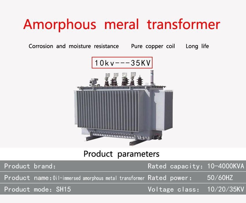
- Commodity name: Rectifier Transformer Diagram
The mechanical parts (fuel tank) of the distribution transformer are nothing special. However, in electrical design, active components are different from standard transformers. Power electronic circuits can convert alternating current (ac) into direct current (dc). These are called rectifier circuits. The vice versa also applies to power circuits called inverter circuits.
The rectifier transformer is the link between the grid and the AC/DC converter.
The mechanical parts (fuel tank) of the distribution transformer are nothing special. However, in electrical design, active components are different from standard transformers. Power electronic circuits can convert alternating current (ac) into direct current (dc). These are called rectifier circuits. The vice versa also applies to power circuits called inverter circuits. A transformer whose winding is connected to one of these circuits is regarded as a converter or rectifier transformer. The operation of the semiconductor rectifier generates harmonic voltages and currents. Nowadays, electronic circuits provide many types of controls, and in practice they are increasing. These circuits are usually more effective than previous control types. Rectifier circuits are used to provide high-current direct current for electromechanical processes such as chlorine production and copper and aluminum production. They are also used for variable speed drive motor control, transportation traction applications, mining applications, electric furnace applications, high voltage laboratory type experiments, high voltage direct current transmission (HVDC) static dust collectors, etc. The frequency of the harmonic current is higher than the fundamental frequency of the transformer. The problem lies in the harmonic currents. These high frequency currents will cause high levels of eddy current losses and other stray losses in other parts of the transformer. This may generate high temperatures, which will reduce the insulation performance of the transformer and may lead to premature failure of the transformer. Therefore, the idea is to carry out such a design to withstand and overcome the effects of harmonic currents. We usually limit the magnetic flux density and current density to a certain level, and integrate an electrostatic shield between the primary winding and the secondary winding. Compared with standard transformers, rectifier transformers have a larger footprint, are heavier and more expensive. Compared with standard transformers, rectifier transformers have a larger footprint, are heavier and more expensive. We usually limit the magnetic flux density and current density to a certain level, and integrate an electrostatic shield between the primary winding and the secondary winding.


Related products

Communication and Support
Welcome to Tianyi Incorporate, if you are interested in our products, please submit your contact information and we will arrange a professional engineer to discuss with you as soon as possible!
